The main concept that test-takers need to comprehend to maximize their score fully is the CompTIA A+ motherboard diagram. For this reason, everything you ought to know about this subject will be covered in this post.
Check out our free CompTIA A+ practice test to pass the actual exam with a flying score.
General Information of CompTIA A+ Motherboard Diagram
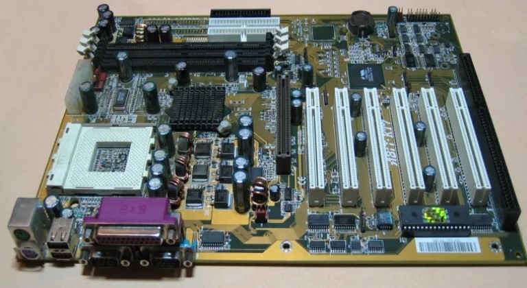
The motherboard (also known as Motherboard) is also referred to by other names such as MB, mainboard, backplane board, baseboard, main circuit board, planar board, system board, or on Apple computers, it is called the Logic board. The motherboard is a circuit board that serves as the foundation of a computer set, located in the center of the case. It distributes power to the CPU, RAM, and other computer hardware components. Most importantly, the motherboard establishes the connection between these components.
Structure
The printed circuit board of the motherboard has a slightly different structure than the printed circuit board of other commonly found electronic devices. In simple circuits, most printed circuit boards have a double-sided structure (front and back) to accommodate the paths on them.
Due to the presence of multiple paths operating at different frequencies, the board must be designed in a way that prevents interference between them. This distinction sets the motherboard’s board design apart from ordinary circuit boards. Motherboards, which contain numerous components with large paths, are typically designed with 3 to 5 layers (or even more). In addition to the front and back layers, there are additional layers within the board that serve as guides for the circuit paths.
Functions of Motherboard
- Booting the motherboard after power-on
- Binding components in a computer system together
- Controlling BUS speed changes to accommodate different components
- Managing power for components on the mainboard
- Providing a master clock (Clock pulse) to synchronize the operation of the entire system.
Main Components
-
Chipset (including Southbridge and Northbridge): The chipset plays a crucial role in bringing data from the hard drive, through memory, and to the CPU. It ensures that peripherals and expansion cards can communicate with the CPU and other devices.
-
BIOS: This is the basic input/output system, which is equally important as the chipset in each main server. The BIOS contains the system’s working parameters and is either soldered and glued directly to the main server or plugged into a socket for easy disassembly by users.
-
Socket: The socket refers to the number of CPU pins on the motherboard. The socket type of the CPU you wish to purchase must be compatible with the supported motherboard.
-
CPU: The standard slots for AMD and Intel processors are different. Therefore, you cannot plug a processor from one company into a motherboard that supports the other company’s processor. Store processors also use different slots, making upgrades difficult in many cases.
-
Bus system: This indicates the maximum operating frequency of the data communication line of the CPU that the motherboard supports. A high-speed bus will also support lower bus processors.
-
ISA slot: This slot was traditionally used to plug in additional expansion boards such as video and audio boards. However, the ISA slot is no longer integrated into modern motherboards.
-
PCI slot: The PCI slot is used to install additional communication devices with the computer, such as sound cards and internal modems.
-
PCI Express slot: The PCI Express slot supports significantly more bandwidth than the PCI standard and is capable of replacing both PCI and AGP slots.
Read more >> CompTIA A+ Cable Types & Connectors with Their Purposes
Motherboard Form Factors
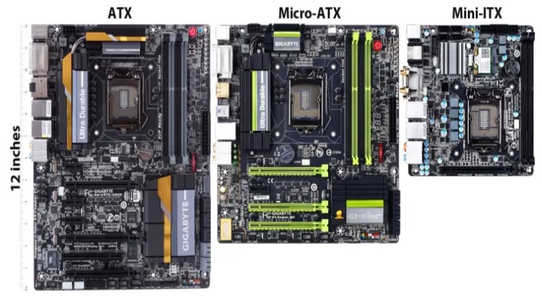
The form factor can be understood from an equipment planning perspective, as it defines and specifies the size, shape, and other physical details of components, especially in electronics. It can also refer to the overall structure of a system, such as a computer case. Computer chassis are designed to accommodate specific form factor components, and a CompTIA A+ technician needs to know these common standard form factors.
ATX (Advanced Technology eXtended)
Advanced Technology eXtended (ATX) is the most common form factor for desktop cases and motherboards. It was introduced by Intel as a replacement for the old AT design. ATX is an evolutionary design that builds upon the previous Advanced Technology (AT) model, improving the case outline, power supply, and motherboard. With better utilization of space and resources, ATX has quickly become the default form factor for most new PC systems. Today, the industry widely accepts the ATX form factor as the standard.
ATX brought significant changes to motherboard designs and became the default form factor for modern systems due to its advancements in I/O devices and processor technology. It made it easier to add or remove components. Additionally, ATX is more cost-effective than previous form factors.
ATX motherboards are designed with modules that work together more efficiently, thanks to the optimal placement of each component. With the drive and power supply located in a more convenient position, connecting the motherboard becomes easier. By minimizing the length of cables on the motherboard, the risk of data corruption and electromagnetic interference (EMI) is reduced.
An additional highlight of ATX motherboards is the placement of the power supply fan. Airflow is directed directly onto the processor and expansion cards, improving cooling efficiency and reducing noise. Another notable feature of ATX is the inclusion of a soft switch or soft power control.
The soft switch is controlled by the operating system, providing a gentle power shutdown when the system is turned off using the power switch. In older systems, abruptly cutting off power when using the power switch can lead to errors during reboots and put additional strain on the motherboard.
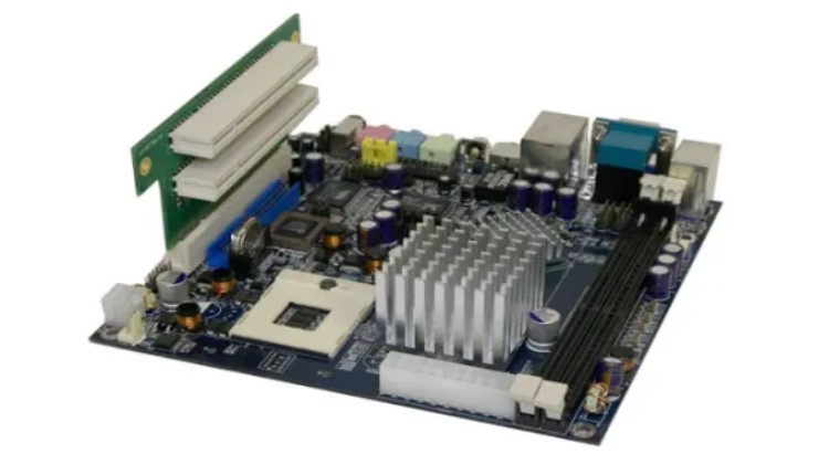
ITX (Information Technology eXtended)
ITX, which stands for Information Technology eXtended, is most commonly known as the Mini-ITX version. It is a small 170×170 mm mainboard that was introduced to the market in 2001 by VIA Technologies for use in compact computer systems. Initially, the ITX mainboard standard aimed to maximize mobility and reduce overall costs, but due to various factors, the latter cost increased.
Essentially, a Mini-ITX-based system can be considered a desktop computer with mobile features, thanks to its surprising compactness. In situations where mobility is required, and the power of a desktop system is necessary, which a laptop may struggle to provide, an ITX case becomes an excellent solution. It is ideal for activities such as live online gaming, 3D design, graphics tasks, and other activities that demand a stable system. These scenarios benefit from a compact case that utilizes an ITX mainboard.
In addition to its optimal functionality, ITX mainboard rigs have also become a passion for technology enthusiasts. Imagine a system that is as compact as possible (with the condition of being portable), yet packed with features like a larger case, while still ensuring effective heat dissipation. Achieving this requires a wealth of knowledge, as well as careful investment and arrangement of components.
Motherboard Connector Types
Motherboards utilize expansion slots to provide support for additional input/output (I/O) devices and high-speed video/graphics cards, with the most common expansion slots being PCI Express (also known as PCIe for short).
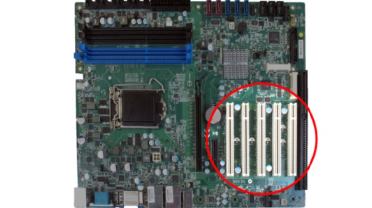
PCI Slots (Peripheral Component Interconnect)
PCI is an acronym for Peripheral Component Interconnect, which refers to the communication standard between computer hardware components. It determines the compatibility between different parts of the computer system. The PCI standard is commonly used for motherboards, RAM, graphics cards, sound cards, network cards, mice, keyboards, and computer speakers. Different PCI standards provide varying transfer speeds and handle different data loads. On the other hand, PCIe (PCI Express) is a communication standard known for its high data transmission speed.
PCI was introduced by Intel in 1992. The PCI bus comes in both 32-bit (133MBps) and 64-bit versions and is used to connect hardware to computers. While it was commonly used in computers from the late 90s to the early 2000s, PCI has been replaced by PCI Express. Several versions of PCI Express were released, including version 2.0 in 2003 and version 2.1 in 2005, as extensions to the ISA bus. Unlike ISA and previous expansion cards, PCI follows the Plug and Play (PnP) specification, eliminating the need for jumpers or embedded switches.
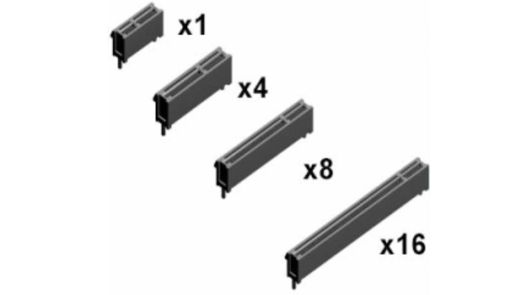
PCIe (PCI Express) Slots
PCIe, or PCI Express, is a generation of PCI interface standards that offer higher data transfer rates compared to conventional PCI. It primarily refers to the connections between expansion card components, computer RAM, and the computer motherboard. PCIe 4.0 is the latest communication standard and provides the highest data transfer rate available today. It supports maximum speeds up to 16GT/s and a bandwidth of 64GB/s. On the other hand, PCIe 3.0 is the most widely used communication standard between computer components.
PCIe is a high-speed serial computer expansion transport standard designed to replace the older PCI transport standards. It serves as the standard motherboard interface for various components, including graphics cards, hard drives, SSDs, WiFi, and Ethernet connections. PCIe offers advancements over the older standards, including higher maximum throughput, increased I/O lane count, smaller physical footprint, improved scalability, enhanced error detection capabilities, and native hot-swap functionality.
Newer versions of the PCIe standard also provide hardware support for I/O virtualization. PCIe slots are available in four different types: x1, x4, x8, and x16. (Each ‘x’ refers to an I/O lane.)
Riser Cards
A riser card is a printed circuit board that collects multiple signal lines, often used, through a single connector (usually an edge connector) on a motherboard and delivers them through dedicated connectors on the card. Riser cards are commonly used to enable expansion cards or other ports to be accessible in a system enclosed in a low-profile case, where the case height does not allow for the installation of a full-height expansion card in the conventional position.
Socket Types
In computer equipment, a CPU socket (or CPU slot) contains one or more mechanical components that provide mechanical and electrical connections between a chip and a printed circuit board. This allows for the placement and replacement of the CPU without soldering. Common sockets have retention clips that apply a constant pressure, which needs to be overcome when a device is inserted.
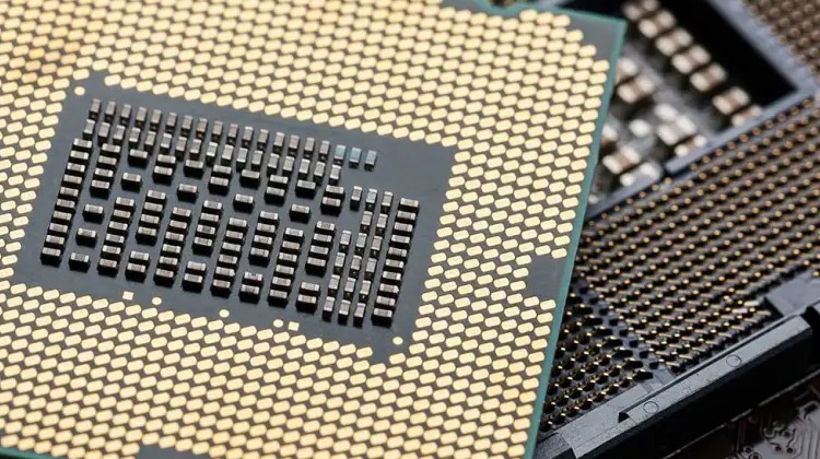
For chips with numerous pins, zero insertion force (ZIF) sockets are preferred. Common socket types include PGA (Pin Grid Array) and LGA (Land Grid Array). These designs apply compression pressure once a lever (for PGA type) or a surface plate (for LGA type) is put into place. This provides superior mechanical retention while avoiding the risk of bending pins when inserting the chip into the socket.
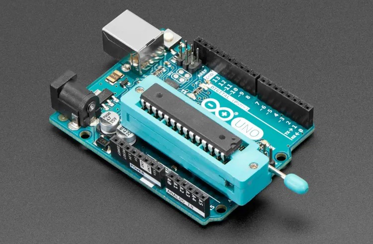
ZIF (Zero Insertion Force) is a type of integrated circuit (IC) or electrical connector that requires very little force for insertion. With a ZIF socket, a lever or slider on the side of the socket is moved, pushing all the sprung contacts apart so that the IC can be inserted with minimal force, often the weight of the IC itself is sufficient, and no external downward force is required.
The lever is then moved back, allowing the contacts to close and grasp the pins of the IC. ZIF sockets are generally more expensive than standard IC sockets, as they tend to require a larger board due to the space taken up by the lever mechanism. They are typically used when there is a specific need to do so.
LGA, which stands for Land Grid Array, is a packaging technology that features a rectangular grid of contacts on the underside of a package. The LGA design uses spring-loaded lands within the processor socket that connect to bumps on the backside of the processor. The number of lands within the processor socket is used to determine the numeric part of the socket designation.
For example, LGA 775 indicates that there are 775 lands within the processor socket. Not all rows and columns of the grid need to be used. The contacts can be established either by utilizing an LGA socket or by using solder paste.
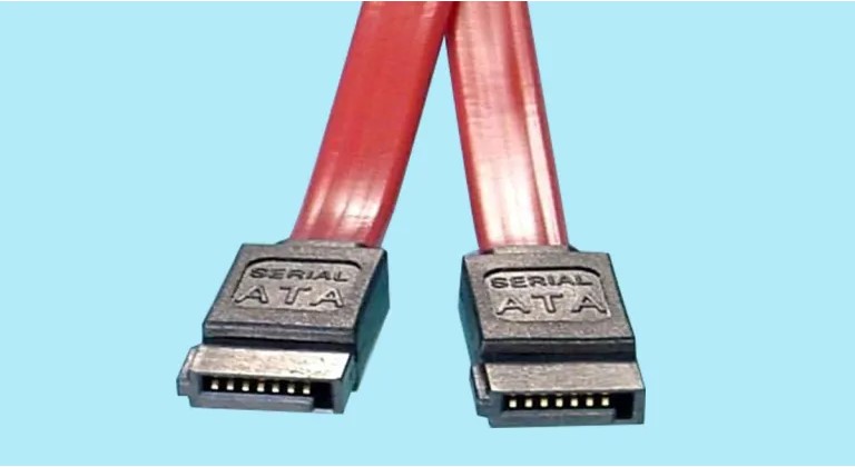
SATA & IDE
Serial ATA, also known as SATA, is a computer transport interface that connects storage connectors to mass storage devices such as hard disk drives, optical drives, and solid-state drives, located near the CPU. SATA connectors replaced IDE connectors, which were ribbon-like cables used for CD-ROMs/DVDs or slower and bulkier hard drives that required separate configurations.
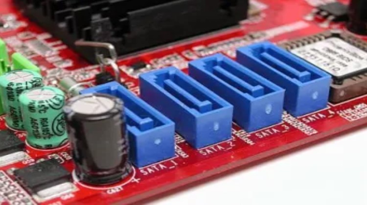
SATA, moreover, succeeded the earlier PATA (also known as Parallel ATA) standard to become the dominant interface for storage devices. The most significant improvement was in speed, with first-generation SATA cables transferring data up to 1.5Gbps. As SSDs entered the market, the SATA specification improved to 3Gbps to match the faster data capabilities of solid-state drives. The latest SATA iteration transfers data at 6Gbps.
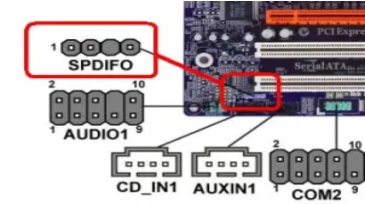
Front & Top Panel Connectors
Ordinary motherboards feature one or more audio connectors designed for various purposes:
- Front/top-panel audio: Microphone and headphones; found on nearly all motherboards.
- Music CD playback from optical drives: This feature is rarely required since media player programs can play music through the SATA interface.
- SPDIF header: Intended to support an optional SPDIF bracket for digital audio playback.
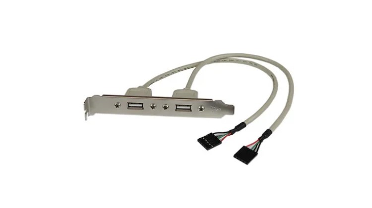
Internal USB Connector
The USB connector on the exterior of the case or laptop provides an interface to the motherboard, allowing external devices to access the motherboard.
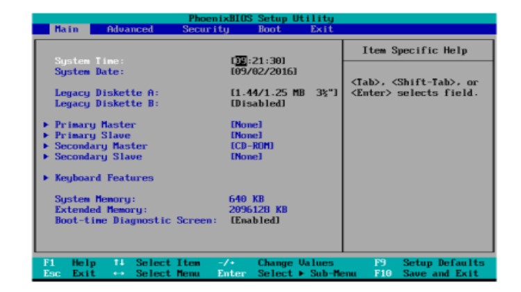
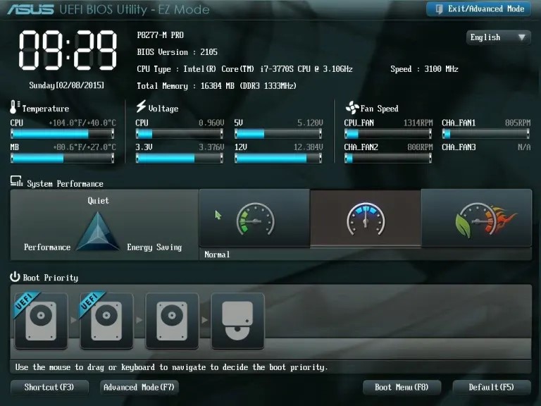
BIOS/UEFI Settings
BIOS, which stands for Basic Input/Output System, is a ROM chip commonly found on motherboards. It allows you to access and configure your computer system at the most fundamental level. On the other hand, UEFI, which stands for Unified Extensible Firmware Interface, is a detailed interface between an operating system and a platform program.
UEFI is the primary code run by a computer when it is booted. It prepares the machine by testing its components during bootup and paves the way for the operating system to start. It tests and initializes components such as the processor, optical drives, video cards, hard drives, and USB drives.
Read more >> What Should You Know About CompTIA A+ Troubleshooting Model?
If any errors occur, the BIOS/UEFI reports them as part of the testing process, commonly known as the POST (Power-On Self-Test). To access the BIOS, press the key or key combination displayed on the screen when the system starts booting to enter the BIOS program menu.
UEFI, which can be a GUI or text-based menu, has replaced the legacy BIOS firmware interface in most computers. Most UEFI firmware implementations also provide support for legacy BIOS services. UEFI can support additional diagnostics and repair of computers, even without an operating system installed. All Mac computers use UEFI firmware.
Pros of UEFI:
- Support for hard drives with a capacity of 2TB and higher. These drives require the use of GPT (GUID Partition Table) to access their full capacity.
- Faster system startup and other optimizations.
- Larger ROM chips used by UEFI allow for additional features, improved diagnostics, the ability to access a shell environment for easy firmware updates, and the capability to save multiple BIOS configurations for reuse.
Firmware Updates
Common steps to find and install a BIOS update:
-
Go to the vendor’s website and look for “downloads” or “tech support” links. The BIOS updates are listed by system model and version. Avoid beta (pre-release) versions.
-
Locate the correct BIOS update for your system or motherboard.
-
Determine the installation media required to install the BIOS image (such as a Windows-based installer, bootable CD, or USB flash drive).
-
Download all the files required to install the BIOS image.
-
Create bootable media and then follow the vendor’s instructions to place the loader and BIOS image files on the media.
-
Installation
- Bootable media: Make beyond any doubt the drive the primary thing within the BIOS boot arrangement. Embed or interface your media and restart the framework. In case provoked, press a key to begin the updated handle. After the method begins, it takes roughly three minutes to rewire the substance of the BIOS chip with the upgraded information.
- Windows: Near all Windows programs before the process of beginning the upgraded handle. Explore the envelope containing the BIOS overhaul and double-click it to begin the upgraded handle. Take after the prompts onscreen to total the method (takes around 3 minutes).
- Evacuate the media and restart the framework to utilize your modern BIOS highlights. Reconfigure the BIOS settings in the event necessary.
Caution: While performing a BIOS update, ensure that you do not turn off the power to your computer. Wait for a message indicating that the BIOS update has been completed before interacting with the computer. If the power goes out during the update process, the BIOS chip may become unusable.
Security Features
Security features of various types are scattered throughout the typical system BIOS/UEFI dialogs. The features and their locations vary depending on the system and may include:
- BIOS password: Found in BIOS Settings Password or Security dialogs. Enabling a BIOS password allows access to BIOS setup dialogs.
- Power-on password: Configured through the Security dialogue. Prevents anyone without a password from starting the system.
- Chassis intrusion: Located in different sections.
- Boot sector protection: Available in the Advanced BIOS Features dialog.
Note: BIOS password and power-on password can be bypassed by opening the system and clearing the CMOS memory.
The following features are capable of supporting drive encryption:
-
Trusted Platform Module (TPM): Found in the Security dialogue. Windows versions that support BitLocker Full Disk Encryption (FDE) feature TPM to secure the contents of specified drives.
-
LoJack for laptops: An aftermarket product that is either embedded in firmware or installed by end-users. It is not managed through BIOS dialogs. LoJack is used for locating lost or stolen laptops.
-
Secure Boot: Found in the Boot or other dialogs. It prevents the installation of other operating systems and requires the user to access the UEFI setup by restarting the computer in a special troubleshooting mode within Windows 8 or later.
Interface Configurations
The interface arrangements include:
-
SATA configuration options: These options allow you to enable/disable SATA and eSATA ports and configure SATA host connectors to operate in different modes such as incompatible, native, or RAID.
-
USB port configuration and charging support: These settings are used to enable USB 2.0 and 3.0 in your system BIOS, ensuring that all your system’s USB ports operate at the appropriate speeds.
-
Audio and Ethernet port configurations: These settings are used to configure audio and other integrated ports, including Ethernet ports, for optimal performance and functionality.
CMOS Battery
The CMOS battery, which stands for complementary metal-oxide-semiconductor, maintains the time, date, hard disk, and other setup settings within the CMOS memory. CMOS batteries are small and directly attached to the motherboard. They provide power to preserve the contents of the CMOS chip.
The battery life is typically several years, but a low CMOS battery can cause issues with drivers and sometimes affect the booting process. Errors in system date and time can be a sign that it is time to check or replace the battery. To clear the CMOS on most systems, place a jumper piece over two jumper pins. Some systems feature a port-cluster-mounted push button for clearing the CMOS.
Read more >> CompTIA A+ Port Numbers: Important Things to Know in 2024
CPU Features
CPU Cores: Single Core and Multicore
A single-core processor is a chip with one CPU (central processing unit) that receives data from the computer program to perform calculations for output. On the other hand, multicore processors are computer processors that contain circuits with two or more independent processing units. These units analyze and execute program data as if the computer had multiple processors. The advantage of a multicore processor over having multiple physical processors is a reduction in cost, and they are compatible with any operating system that supports traditional single-core processors.
Virtualization
CPU virtualization emphasizes performance and runs directly on the processor whenever possible. It utilizes the underlying physical resources as much as possible, and the virtualization layer functions transparently to make virtual machines operate as if they were running directly on a physical machine. Most modern processors feature virtualization support, also known as hardware-assisted virtualization. Hardware-assisted virtualization enables virtualized operating systems and applications to run faster and utilize fewer system resources.
Hyperthreading
“Hyperthreading is Intel’s proprietary implementation of concurrent multithreading used to enhance the parallelization of computations (performing multiple tasks at once) on an x86 chip. When hyperthreading is enabled in the system BIOS and the processor is running a multithreaded application, the processor simulates two physical processors.
CPU Speeds
A bus is a circuit that connects various components of the motherboard, such as the CPU, memory, chipsets, expansion slots, storage interfaces, and I/O ports. The capacity of a bus to handle data at a given time determines the speed at which information can travel. The speed of the bus, measured in MHz, indicates how much data can be transferred over the bus simultaneously.
Overclocking
In computing, the purpose of overclocking is to increase the operating speed of a given component. In modern systems, the goal of overclocking is to enhance the performance of a major chip or subsystem, such as the processor or graphics controller, although other components, such as system memory (RAM) or system buses, are commonly involved. The trade-offs of overclocking include increased power consumption (heat), fan noise (cooling), and a shortened lifespan for the targeted components.
Most components are designed with a safety margin to handle operating conditions beyond the manufacturer’s control. Overclocking methods typically involve pushing beyond this safety margin by setting the device to run at the upper limit of its capabilities, with the understanding that temperature and voltage must be more closely monitored and controlled by the user.
Integrated Graphics Processing Unit
An IGP (Integrated Graphics Processing) unit is a graphics chip that is integrated into a computer’s motherboard. The IGP serves the same purpose as a video card, which is to process the graphics displayed on the computer. The IGP offloads the graphics portion of the processing load from the CPU.
Because IGPs are integrated into the motherboard, their size is limited, and they cannot utilize a dedicated fan for cooling as some video cards do. This is typically the main reason why IGPs often do not have the same performance as dedicated video cards, as they are connected to the computer’s PCI or AGP ports. However, due to their small size, IGPs are suitable solutions for tablet computers and entry-level desktop PCs.
Processor Compatibility
AMD and Intel are the two primary companies that manufacture CPUs. AMD processors utilize the PGA (Pin Grid Array) form factor, where the contact pins that insert into the socket are mounted on the CPU itself. In contrast, Intel processors utilize the LGA (Land Grid Array) form factor, where the pins that connect the CPU to the motherboard are mounted on the motherboard’s socket. The physical joining and internal workings of the CPUs mean that the two brands are not compatible with each other. However, independent motherboard manufacturers such as ASUS and ASRock produce various boards that support CPUs from both companies.
Read more >> CompTIA A+ Linux Commands | The Complete Guide in 2024
Cooling Mechanisms
Computer cooling is necessary to dissipate the waste heat generated by computer components and to maintain components within acceptable operating temperature limits. Components such as integrated circuits (CPUs), chipsets, graphics cards, and hard disk drives are susceptible to temporary malfunction or permanent failure if overheated.
The primary requirements for proper CPU cooling include the use of an appropriate heat sink (which includes a fan) and the application of a suitable thermal compound (such as oil, paste, or a pre-applied thermal or phase-change compound). Advanced systems sometimes utilize liquid cooling as an alternative method.
Expansion Cards
An expansion card, also known as an expansion board, is an electronic card used to add additional functionality to a computer. It is inserted into an expansion slot on the computer’s motherboard. Expansion cards feature edge connectors that establish an electronic connection between the motherboard and the card, enabling communication between the two.
Video Cards
A video card, also known as a graphics card or display adapter, is an expansion card that generates output images for a display device, such as a computer monitor. Most video cards are not limited to basic display output. Their integrated graphics processor can perform additional processing, relieving this task from the computer’s central processor. Video cards can come as onboard components integrated into the motherboard or as add-on cards that can be installed separately.
Sound Cards
A sound card is a circuit board that enables a computer to produce audio, which can be heard through speakers or headphones. While not necessary for a computer to function, a sound card is included in every machine, either as a separate card inserted into an expansion slot or integrated into the motherboard.
Conclusion
Knowing the CompTIA A+ motherboard diagram mentioned earlier can assist you in successfully passing the CompTIA A+ certification test and advancing your career as an IT expert.

PCCN vs CCRN: Which Certification Should I Take?
In this discussion, we will examine the fundamental distinctions between PCCN vs CCRN certifications, allowing you to make an informed and right decision about which certification is best for your nursing career progression.
June 20, 2023
Is PCCN Worth It? A Comprehensive 2024 Study Guide
In this article, we will provide all the enrollment criteria, how to apply, whether is PCCN worth it for you to obtain, and how to get a high mark.
June 20, 2023

PCCN Requirements - How to Become a Progressive Care Certified Nurse?
To become a progressive care nurse, you must first obtain the PCCN certification. This post will help you understand PCCN certification, PCCN requirements, and efficient approaches to obtaining this certification.
June 20, 2023